The 32 ft wing
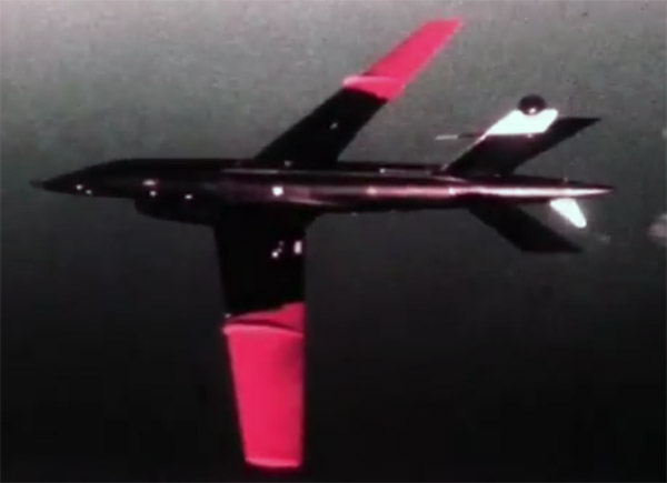
Early on in the Model 147 / AQM-34 program, a 27 ft span wing was developed. At a later stage, around 1967, a yet bigger wing was developed, to achieve higher operating altitudes (65,000+ ft) and increased range (2400+ miles). This wing has three designations: '32 ft wing' / '114 sqft wing' / 'H-wing'.
| Item | Dimension | Comments |
| Area (gross) | 114.4 sqft | area agrees with chord and span data. Excludes root fairing. the center wing area is 78 sqft, the outboard wings add 36 sqft |
| Span | 384.0 in (32' 0.0") | TO-21M-AQM34-3, Figure 1-7 (see below) suggests the span figure excludes the anti-flutter mass tube |
| Root chord (BL 0) | 61.2 in (5' 1.2") | the outline in TO-21M-AQM34-3, Figure 1-7 (see below) agrees visually with this number |
| Tip chord (BL 192) | 24.6 in (2' 0.6") | the outline in TO-21M-AQM34-3, Figure 1-7 (see below) agrees visually with this number |
| Quarter chord sweep | 24 deg | TO-21M-AQM34-3, Figure 1-7 (see below) measures 23.6 degrees |
| Taper ratio | ~0.4 | 0.402 calculated |
| Aspect ratio | ~9.0 | 8.95 calculated |
| Root profile | 64A310 mod | streamwise |
| Tip profile | 64A306 mod | streamwise |
| Root incidence angle | 0 | |
| Twist angle | 0 | |
| Dihedral / anhedral | 0 | |
| Wing fence | BL 115 | calculated local chord 39.2 in |
| Outboard wing joint | angled | |
| Pylon location | BL 46.150 | |
| Structure | three-spar inboard wing, aluminum. Frontmost spar at 22% chord, rearmost spar at 68-69% wet wing composite outboard wing? the relevant Firebees were meant for MARS-recovery, not belly landings, and it appears that the outboard wings were not meant to break off | |
| Notes | used on Models 147H (AQM-34N), 147HR, 147T (AQM-34P), 147TE (AQM-34Q), 147TF (AQM-34R) wet wing, HH-1 article quotes 40 gallons spoilers on upper surface | |
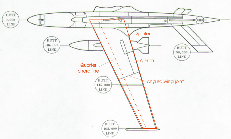
The wing shape was drawn in red over the Tech Order drawing, and it matches very well except for a small sweep angle difference, of about 0.4 degrees. Note that the wing shape in red was constructed, not simple drawn over the the drawing's lines. Source: TO-21M-AQM34-3, Figure 1-7, RPV Station Locations, courtesy of Dave Matthews.
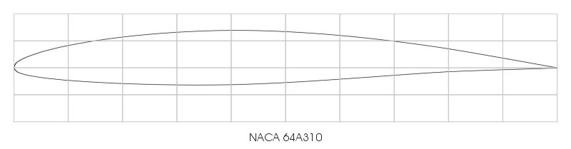
A surplus 32 ft Firebee wing was used for the HH-1 Zipper, a homebuilt aircraft designed and built by Dick Hunt and Bob Hammer (see short bio). Unfortunately the HH-1 crashed after six weeks of test flying. The sketch below (it's not a proper drawing) contains a number of interesting details. It quotes 25 degrees sweep on the leading edge (I calculate 26.2 degrees from the table data), a NACA 65A210 profile (table lists 64A310), a 10-bolt wing tip attachment, and a detailed breakdown of the areas, that could help finding the exact position of the wing joint. Source: article 'Design and fabrication of a high-performance jet aircraft' by Bob Hammer, published in 'Homebuilt experimental aircraft, theory and practice - experimental aircraft symposium, Seattle, June 1975, proceedings'.

I had already constructed the root and tip profiles for the AQM-91A wing and tail profiles, using methods from Abbott & Von Doenhoff. The linked webpage demonstrates the whole process, with lots of number crunching.

The photo archives of Teledyne-Ryan and the former Ryan Aeronautical were donated to the San Diego Air and Space Museum. After a massive scanning effort by Craig Kaston, all 7000+ photos were uploaded to the Flickr photo site, and published in the Ryan Aeronautical Negative Collection collection (a.k.a. 'Ryan Negative Images' collection or 'Teledyne Ryan Archives' collection), without copyright restrictions. This fantastic resource lacks one thing: descriptions of the photos. The museum invites anyone to leave comments on the photo contents, unfortunately with little effect. Most photos shown in this section were found in the collection.
The film archives of Teledyne-Ryan and the former Ryan Aeronautical were also donated to the San Diego Air and Space Museum. After an equally massive digitizing effort, some 4000+ films were uploaded to YouTube, and published in the San Diego Air and Space Museum Archives collection. Apart from the film titles, no other information was supplied with the films. I've identified and listed some 230 Firebee-related films on this Videos page, and some 50 AQM-91-related films on the A+V Models 1/72 AQM-91A Firefly page. The films were another source of material on the 32 ft wing, and film stills are included in this section.
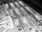
Two photos show the bare internal structure of the inboard wing, seen from the root, without the root rib or the center box in place.

|
|
These three photos probably go together, and show the 32 ft wing's inner structure, with the wing upside down. Details of the wet wing's fuel system can be seen.

|

|
|
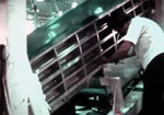
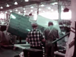
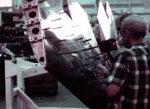
Five screenshots from the film F-0972 Ryan Model 147 The Story of the 'H' Firebee UAV show the new 32 ft wing under construction for the Model 147H. The first photo appears to show a three-spar wing, but I think the 'spar webs' are actually part of the jig. The second photo also shows three spars, plus two heavy stringers in between. In the third and fourth photos the center wing is being closed with the skin, Clecos are visible. The fourth photo also shows part of the outer wing joint. The last photo shows the wing more or less complete, with outer wing panels.

|
|
|
|

|
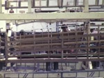
The video F-2712 Boeing B-47, Ryan Firebee RPV, F-4 Phantom yielded three more manufacturing photos of the 32 ft wing. The first photo is confusing, since it shows two wings, one with and one without the outboard sections.

|

|
|
The photo collection yielded another manufacturing photo. It was difficult to establish for sure this was a 32 ft wing, but the small cut-out near the rear spar (upper left in the photo) matched the first screenshot from video F-2712 perfectly. The rivet pattern also agrees with a structure having three spars and a single stiffener between each set of spars.
|
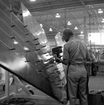
Another great manufacturing photo of the 32ft wing. Among others it shows a narrow panel covering the wing joint, and two puzzling openings in the lower wing skin, on each side, near the root. Considering the presence of a fuselage with a large wing cutout, this is production of a later Model 147T/TE/TF aka AQM-34P/Q/R. Since there seem to be no provisions for pylons, this is likely a Model 147T wing, not one for the Models 147TE/TF that had pylons. The photo is clear enough to do a photo measurement of the front and rear spar chordwise positions.

|
Two photos of structural testing of the new wing were found, dated 1966.

|

|
Bryan Wilburn found an interesting photo that shows the 10-bolt wing joint, just as mentioned in the HH-1 wing drawing.

|
Two photos of an inboard wing waiting for assembly or shipping. The presence of pylons makes this a wing for the 147TE/TF aka AQM-34Q/R.

|

|
Very few photos show the wing of operational AQM-34s with the 32 ft wing in full. This spectacular recovery of AQM-34P / Model 147T with serial 'T-4' is an exception. Four photos were found so far.
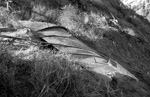
Since the AQM-34P / 147T had a completely new fuselage and camera, and possibly new other systems, I'm guessing the fourth example was used for factory testing. The casual clothing of the recovery crew also suggests Teledyne-Ryan people. In the last photo, the right outboard wing is disconnected, and its crumpled wing tip shows something of its (supposedly) composite structure. Curious are the the two pipes 'pricked' through the wing skin.

|

|

|
|
Bryan Wilburn supplied this interesting drawing, that probably shows the layup schedule of the composite outboard wing, or alternatively the chemical milling pattern.

|