The 27 ft wing
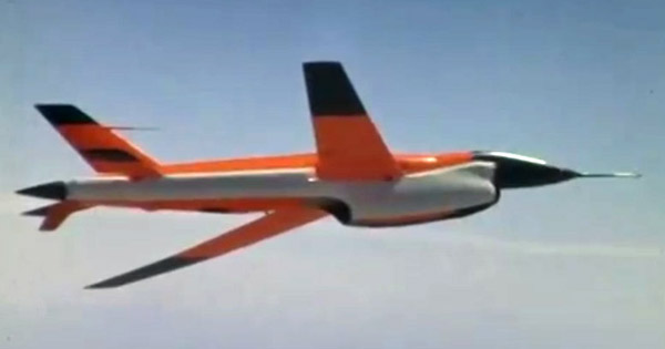
The first version of the 'Lightning Bug' (Model 147A) used the standard BQM-34A wing, fitted with longer wingtips. For the second version, Model 147B, a dedicated wing was developed, better suited to the high-altitude mission. This wing has three designations: '27 ft wing', '80 sqft wing' and 'B-wing'.
Little solid data on this wing was presented in the main references, but by combining lots of sources, a fairly complete picture of this wing appeared.
| Item | Dimension | Comments |
| Area (gross) | 79.6 sqft | area agrees with chord and span data. Excludes wing root fairing, if present. |
| Span | 321.3" (26' 9.3") | |
| Root chord (BL 0) | 51.0" (4' 3.0") | |
| Tip chord (BL ?) | 20.4" (1' 8.4") | |
| Quarter chord sweep | 32 deg | |
| Taper ratio | 0.4 | calculated |
| Aspect ratio | 9.0 | calculated |
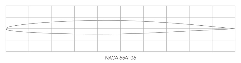
| Root profile | 65A110
or 65A210 mod | streamwise. Possibly not the centerline profile, but the profile at the fuselage side |
| Tip profile | 65A106
or 65A206 mod | streamwise |
| Root incidence angle | 3 deg | |
| Twist angle | 0 | |
| Dihedral / anhedral | zero | incidence angle plus sweep create a visual impression of anhedral |
| Outboard wing joint | ? | BL 96 measured in 'Lightning Bugs' sketch BL 100 is also suggested |
| Structure | Conventional sheet metal construction for both main wing and wing tips Probably three-spar structure Double piano hinge wing tip connection The wing centersection appears to connect to the same points on the fuselage as the BQM-34A wing | |
| Wing root fairing | no wing root fairing on Model 147B
small wing root fairing on Model 147E large wing root fairing on Model 147J | |
| Notes | used for Models 147B, 147E, 147G, 147J
small hatch in front of aileron | |
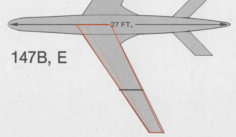
'Lightning Bugs and other reconnaissance drones' contains a simple sketch of the 27 ft wing. I overlaid it with the planform as defined in the table, and the fit was pretty good.
A big unknown however is where the wing was positioned on the fuselage. No data was found. Just maybe, the position of 25% Mean Aerodynamic Chord was kept the same?
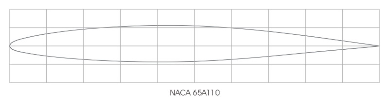
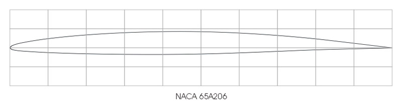
I constructed the root and tip profiles used a method established in my analysis of the AQM-91A wing and tail profiles, using methods from Abbott & Von Doenhoff. I found one reference that listed more 65A series coordinates: Public Domain Aeronautical Software - Appendix III - 6A-Series Sections. My own derived 65A210 profile matched that of Public Domain Aeronautical Software perfectly.
The difference between 65A110 and 65A210, and similarly 65A106 and 65A206, is that the 200 series profiles have a bit more camber than the 100 series.
The profiles are listed as '65A210 mod' and '65A206 mod', but it is not possible to figure out the 'mod' part. Maybe it's as simple as have a certain material thickness at the trailing edge, maybe it's more - we will never know. The fit of these profiles over photos is bad (see below), raising more questions about these profiles.

The photo archives of Teledyne-Ryan and the former Ryan Aeronautical were donated to the San Diego Air and Space Museum. After a massive scanning effort by Craig Kaston, all 7000+ photos were uploaded to the Flickr photo site, and published in the Ryan Aeronautical Negative Collection collection (a.k.a. 'Ryan Negative Images' collection or 'Teledyne Ryan Archives' collection), without copyright restrictions. This fantastic resource lacks one thing: descriptions of the photos. The museum invites anyone to leave comments on the photo contents, unfortunately with little effect. Most photos shown in this section were found in the collection.
The film archives of Teledyne-Ryan and the former Ryan Aeronautical were also donated to the San Diego Air and Space Museum. After an equally massive digitizing effort, some 4000+ films were uploaded to YouTube, and published in the San Diego Air and Space Museum Archives collection. Apart from the film titles, no other information was supplied with the films. I've identified and listed some 230 Firebee-related films on this Videos page, and some 50 AQM-91-related films on the A+V Models 1/72 AQM-91A Firefly page. The films were another source of material on the 27 ft wing, and film stills are included in this section.
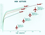
This chart shows design studies. Craig Kaston notes: "Here's how Ryan got to the 80 sqft wing - I think this preliminary work was actually done for the Army 124F (or 124-F) in 1961, before the 147B came about."
|
Bryan Wilburn found another interesting photo, showing a set of wing fences and wing tips. Judging from the size, they are parts for windtunnel tests. Considering the experimenting seen in the videos analyzed above, they are presumably for the 27 ft wing. When corrected roughly for perspective (second photo), the wing tip pieces measure appr. 4.5", the middle fences appr. 6" (or 5.5" excluding the nose piece). Compared to the wing tip chord of 20.4", this suggests a 1:4 to 1:5 scale model.
Bryan commented: The 'nose' of the wing fence protrudes ahead and below the wing leading edge, the aft end stops at the trailing edge, and does not protrude below the trailing edge. The 147E had wing tips that extended above and below the wing tip [possibly for antennas?]. All other end plates only extended below the wings.

|

|
Two manufacturing photos were found, that show the inboard wing at an early stage of assembly, with and without ribs.


|
The first two photos are related. The first one gives a great overview of the bare inboard wing. The second photo shows the inboard side of the wing joint. The third photo shows the wing skin of the inboard wing, before installation. The fourth photo shows the centerbox, with the same four-bolt attachment to the fuselage as the original BQM-34A wing.

|

|

|

|
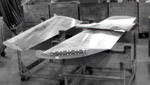
Bryan Wilburn found two great photos. The first shows a set of outboard wing sections of the 27 ft wing, bare aluminum, under constuction at the factory. They have wing fences and endplates fitted. The second shows the piano hinge being fitted. The wing fence looks a little taller than those seen in the videos.
|

|
Bryan Wilburn found another interesting photo in the collection. It shows a a near-perfect side view of the outboard side of the wing joint. In the second photo, Bryan corrected it a bit of lens/perspective correction in Photoshop. The following analysis includes some assumptions. I measured the local wing section to be 8.8 percent thick. I calculated the 65A208.8 profile, and overlaid the profile contour on the photo. The fit is not bad.

|

|

|

|
Two screenshots from F-1591 Ryan Aeronautical RPV Model 147 Lightning Bug show presumably a Model 147B with 'radar blankets' and a wing fence, plus a similar Model 147B in flight, showing the elegant wing.

|

|
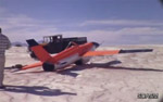
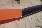
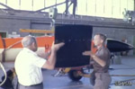
Five screenshots from F-1589 Ryan Aeronautical RPV Model 147 Lightning Bug show a Model 147B after landing, with the left wingtip hinged, as designed, at the outboard wing joint. The wing fence is just outboard of the wing joint, and there's a narrow strip covering the wing joint, seen in the third photo.
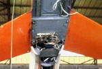
In the fourth screenshot a wing tip is fitted and rotated around the piano hinge joint. It's clearly seen that the hinge line is in the flying direction. No wing tip endplates / skids are seen. The fifth shows the profile at the wing joint. The sixth and seventh photos show how the wing is attached to the upper fuselage. It appears to be bolted to the fuselage with four vertical bolts, just like the original constant-chord wing.
|
|

|
|

|

|
|
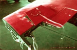
A screenshot from F-0875 Project Firefly Surveillance UAV and Lockheed C-130 Hercules showing the inboard side of the wing joint. The double piano hinges are clearly visible, more on these below.
|
A screenshot from F-1038 Teledyne Ryan 147 UAV showing the wingtip folded during maintenance, as if it were a Navy aircraft onboard an aircraft carrier.

|
A screenshot from F-1039 Teledyne Ryan Firebee UAV 147 showing that the Model 147E had a small wing root fairing.

|
A screenshot from F-1037 Teledyne Ryan 147 UAV in which a wing twist check is performed using templates (pretty unique in itself). Also visible are the aileron, a hatch ahead of it, and the wing joint.

|
These screenshots from F-1588 Ryan Aeronautical RPV Model 147 Lightning Bug show a Model 147B being modified for a wing fence at the wing joint. We see the wing tip being modified, first with an extra hole, then the wing fence is added, then the piano hinge is fitted again. This suggests that the span grew a tiny bit. The last photo supposedly shows the same wingtip, with what looks like three chordwise rows of pressure holes and tufts that are dead straight.
A question marks that this modification raises is how the filler strip now connects to the wingtips side, since the fence is in the way. Also, the fastener holes on the outboard side are superfluous. Newly made wingtips will probable have these holes deleted.
One last question concerns the small red cilinder at the rear end of the lower piano hinge, seen in the third photo. Craig Kaston explains: "It's squib / actuator." He quotes: "The wing tip is designed to be jettisoned on contact with the ground during the terminal phase of parachute recovery. However, the main structural joint between the tip and wing is removed by explosive devices 17.2 seconds after initiation of main chute deployment. A low-load-carrying fairing is then sheared when either wing tip contacts the ground."

|

|

|

|

|
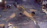
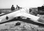
A screenshot from F-2712 Boeing B-47, Ryan Firebee RPV, F-4 Phantom shows presumably a Model 147J, a camouflaged low-level recce variant. It has a wing fence and a wing endplate, and features the largest wing root fairing variant. Years later I found great topside view of this probably unique Firebee in the photo collection. The third and fourth photos are from F-1529 Ryan Aeronautical Model 147 Paris Air Show , that probably show the same Firebee. It's 11 minutes of a left-side view, in flight, and the footage is duplicated in the 32 minute film.

|
|

|

|
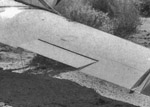
This photo shows the largest wing root fairing used on this wing, and a zoomed-in version with more contrast shows the obround hatch ahead of the aileron.
|
|
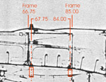
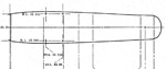
The exact position of the 27 ft wing on the fuselage still is a question mark. This wing shares the fuselage attachment points of the original BQM-34A wing, therefore this was analysed first, using the known frame FS (fuselage station) numbers of two frames. Later, hard data was found in T.O.1Q-2C 'Structural Repair Instructions USAF Model Q-2C Target Drone'. Section 2.2 reports "The wing is secured to the fuselage with four conical fittings and four bolts located at stations 67.75 and 84.00." Figure 2-4 'Wing Jig Positions' shows that the conical fittings are located at Butt Line 12.250. Figure 4-3 'Fuselage Jig Dimensions' confirms the FS and BL positions. This leaves the question where the attachment points are located on the wing planform.
|
|
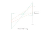
I wanted to know whether the longitudinal position of the 'quarter mean aerodynamic chord' (25% MAC) was a design driver for the 27 ft wing planform. First the BQM-34A wings were analysed, using a simple graphic method. The value found for the short wingtips agreed with Ryan data. Next the 27 ft wing was analysed, but the wing position isn't established yet.

|
|